Raspberry Pi and 1-Wire temperature sensor
Reading temperatures with Raspberry Pi is a good exercise in electronics for more programmer types. There are many instructions on how to use a DS18B20 1-Wire temperature sensor with Raspberry Pi, but in this post I’ll have some Ansible magic and prettier photos.
Setting up Raspberry Pi devices with Ansible was explained in the previous blog post.
I experimented with this setup the first time following Adafruit’s Raspberry Pi Lesson 11. DS18B20 Temperature Sensing.
Required hardware and software
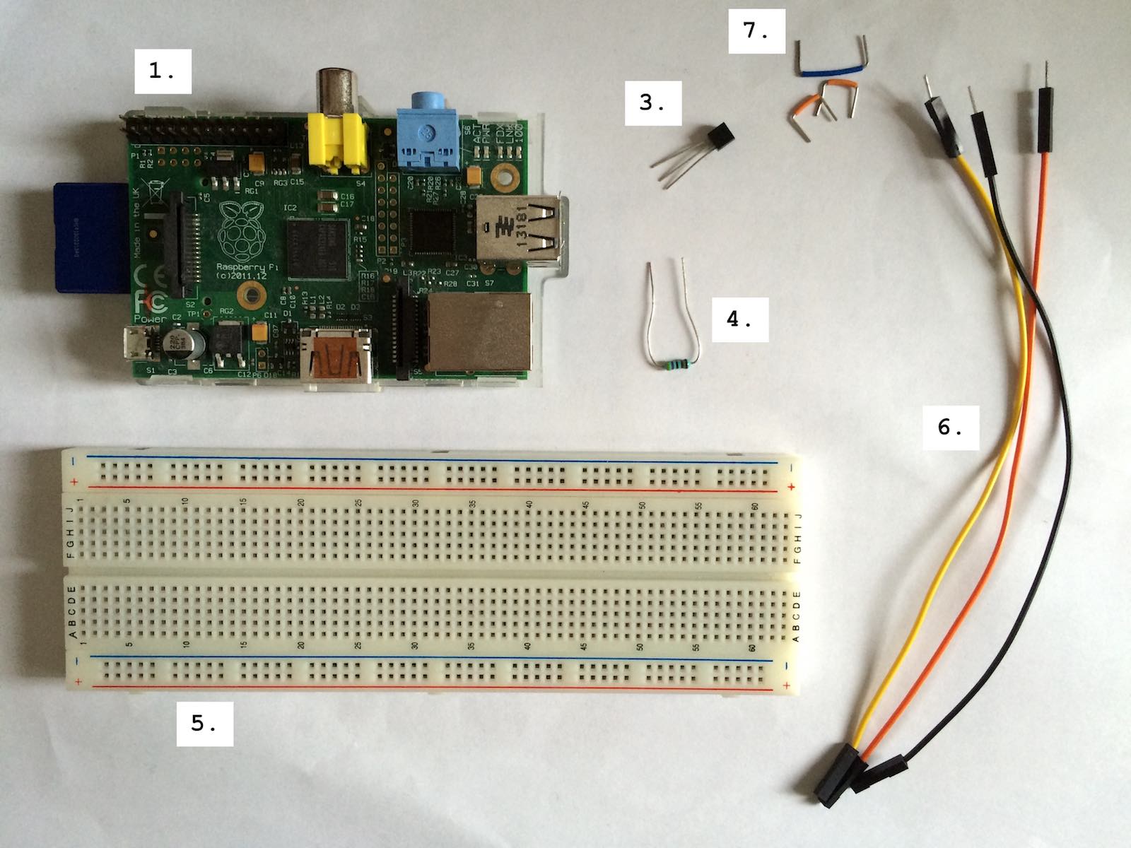
- Raspberry Pi
- Ansible and clone of raspberry-ansible repository configured with correct IP addresses and SSH keys
- DS18B20 digital temperature sensor (datasheet, Finnish electronics vendor)
- 4,7 kΩ or 10 kΩ resistor (Finnish electronics vendor: 4,7 kΩ, 10 kΩ)
- Breadboard (Wikipedia, Finnish electronics vendor)
- Jumper cables from Raspberry Pi to breadboard: male-female (Finnish electronics vendor)
- Jumper cables from and to breadboard: male-male (Finnish electronics vendor)
Raspberry Pi GPIO
GPIO stands for General Purpose Input/Output. These are ports that you can control with software reading and writing bits to and from external devices. GPIO pins are located in Raspberry’s top left corner in the image above (close to the number 1).
The pinout (i.e. which pin does what) is described in the document
GPIO: Raspberry Pi models A and B.
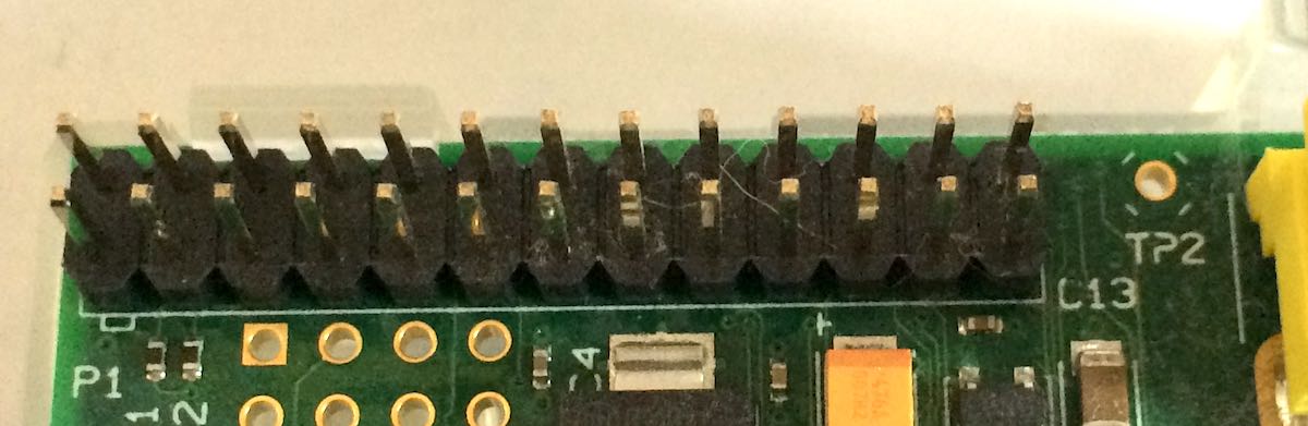
Pinout diagram is shown below, with a close-up photo of the pins. Labels P1 and
L13 are used for reference to make sure that the pinout isn’t upside down.

where 5V and 3V3 stand for +5V and +3,3V DC, GND stands for ground and all
yellow boxes with numbers in them are GPIO data pins. The numbering isn’t in any
logical order, but the numbers are used for identifying those ports in the software.
A good reference with more detailed explanations for these pins is the Raspberry pinout site.
Making the connections
First of all, Raspberry Pi has to be powered off when making the GPIO connections!

Circuit diagram is shown in the image above. DS18B20 uses 1-Wire data transfer protocol, and Raspberry Pi driver for 1-Wire uses GPIO port 4, so the sensor’s middle pin has to be connected there.
4,7 or 10 kΩ resistor is used as a pull-up resistor to keep the data line signal level in a valid range.
The part inside the dashed box will be done in breadboard, and connections from breadboard to Raspberry Pi will be done with the longer jumper cables (number 6 in the required hardware list).
The breadboard is connected internally so that each of the 5-pin slots are connected to each other (horizontally in the above image) and two connected lines run on each side of the boards (vertically, marked with red and blue in the board).
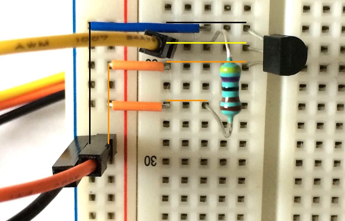
I added the relevant “hidden” connections to the image above:
- Ground (
GND) comes from Raspberry with the black wire to vertically connected blue line, and is connected from there with a blue jumper wire to the top pin of DS18B20 sensor. - Data (
DQ) is the yellow wire that is connected to a 4,7 kΩ resistor and the middle pin of DS18B20 sensor. - +3,3 V (
VDD) is the orange wire that is first connected to the vertical red line, and from there with orange jumper cables to both the other end of the resistor, and to the bottom pin of DS18B20 sensor.
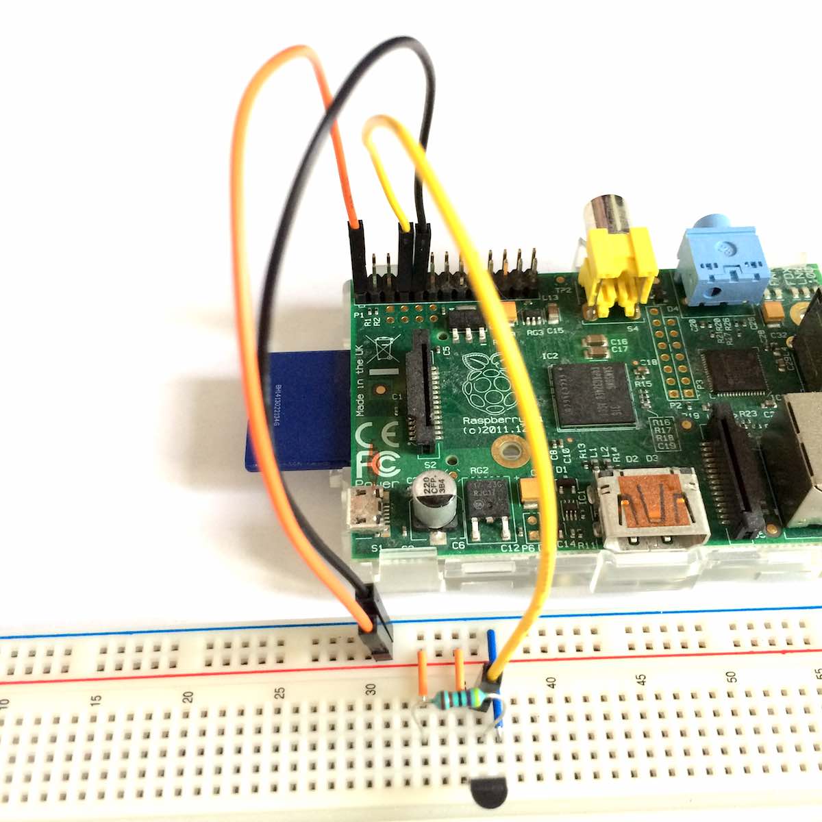
This photo above shows also the connections from breadboard to Raspberry.
Enabling 1-Wire support
The ansible script repository raspberry-ansible has a role and playbook for setting up 1-Wire on the Raspberry Pi device.
It can be run with the following command (assuming you have SSH keys set as explained in the previous blog post):
$ ansible-playbook -i hosts onewire.yml
It will set the Raspberry Pi device tree as w1-gpio, restart the device, load
kernel modules w1-gpio and w1-therm, and add them to be loaded on reboot.
Reading temperatures
Finally it’s time to read some sensor data. w1-gpio and w1-therm drivers create
filehandles for each DS18B20 sensor in the following path:
pi@raspberry1:~ $ ls /sys/bus/w1/devices/
28-0000075f24dc  w1_bus_master1
All directories starting with 28- are DS18B20 sensors ending with a unique
hardware id.
For each of those, you can read the temperature from the file w1_slave:
pi@raspberry1:~ $ cat /sys/bus/w1/devices/28-0000075f24dc/w1_slave
99 01 4b 46 7f ff 07 10 79 : crc=79 YES
99 01 4b 46 7f ff 07 10 79 t=25562
where the number t=25562 is the temperature including three decimal points,
i.e. in this case 25,562 °C.
Multiple sensors
As a bonus, adding multiple sensors to the same 1-Wire bus is really easy. Just plug in another DS18B20 with pins connected the same way as the first one and everything just works!
pi@raspberry1:~ $ ls /sys/bus/w1/devices/
28-0000075f24dc  28-0000075f5202  w1_bus_master1
pi@raspberry1:~ $ cat /sys/bus/w1/devices/28-0000075f24dc/w1_slave
9d 01 4b 46 7f ff 03 10 57 : crc=57 YES
9d 01 4b 46 7f ff 03 10 57 t=25812
pi@raspberry1:~ $ cat /sys/bus/w1/devices/28-0000075f5202/w1_slave
a1 01 4b 46 7f ff 0f 10 d9 : crc=d9 YES
a1 01 4b 46 7f ff 0f 10 d9 t=26062
Here we can see that even though the sensors are 2 mm apart, the temperatures are somewhat different. DS18B20 accuracy is ±0,5 °C, so the readings 25,812 °C and 26,062 °C are well within tolerance.